Virtuoso Schematic
Overview
In this tutorial you will learn how to use the Cadence Schematic Capture Tool. You will create a library to hold your work and you will create a 2:1 multiplexor. In the next tutorials you will simulate your 2:1 multiplexor and use it to create a 4:1 multiplexor. The tutorial details every step of the process. You should follow every step exactly as outlined.
Create a Library for Your Designs
Start Cadence and create a library to hold your design. You should name the library EE445 or EE451 depending on which class you are taking. If you don't know how to create a library, refer to the Cadence setup tutorial.
Schematic Design, 2:1 Multiplexor
Create a new cellview in your library.
Library Name: EE445 or EE451 (default)
Cell Name: mux2_1
View Name: schematic (default)
Tool: Composer-Schematic (default)
Library Path File: <your cds.lib file> (default)

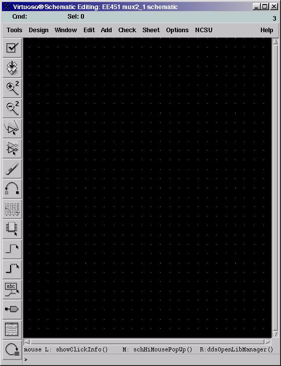
Press OK. The Virtuoso Schematic Editing window appears.

A note about cadence tools. All cadence tools have hotkeys. You will finish your work much quicker and more efficiently if you memorize them. All hotkeys are listed next to their commands in the menu system. For instance, if you choose Add -> Instance... you notice a lower case i next to the command. This is the hotkey. Rather than choosing Add -> Instance... from the menu you can simply press i.
Now you're ready to build your multiplexor.
First, add an inverter, two and gates and an or gate to your design. Select Add -> Instance... or press i. This opens two forms, Add Instance and Component Browser. In the Component Browser form:
Library: NCSU_Digital_Parts
Flatten: Don't Select
Filter: *
Select the inv folder and the inv part. Notice that the Add Instance form was updated automatically. Move your mouse back to the schematic composer window. You should see the outline of an inverter. Place it on the schematic and return to the Component Browser form.
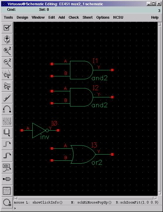
In a similar manner add two and gates and an or gate. Your schematic should look something like the following picture. Don't worry about placement yet.

Press escape to cancel the Add Instance command. You should see the Add Instance and Component Browser windows close.
Note: You should always remember to escape out of commands when you're done with them. I habitually hit escape and save when I'm staring at the screen.
The next step is to arrange the components and wire them up. Select Edit -> Move or press m to be able to move components. Arrange the components like the picture.

Escape out of the move command and select Add -> Wire (narrow) or press w. Wire up the components to match the picture.

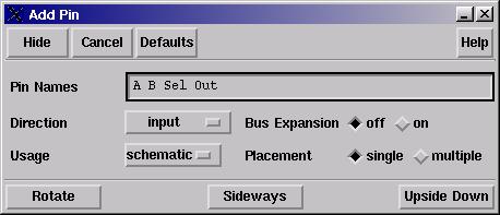
The last step in creating your 2:1 mux is to add pins. Add pins by selecting Add -> Pin... or by pressing p. This opens the Add Pin form. Fill in the names of the pins you will add to the schematic.

Notice the direction drop down box. Place the first three pins as inputs by making sure the direction box says input and clicking on the wire ends on the schematic where you want the pins. Change the direction to output before placing the final pin.
Your schematic should now look like this.

Check and save your schematic by selecting Design -> Check and Save or pressing f8. You should see three new output lines in the CIW:
Extracting "mux2_1 schematic"
Schematic check completed with no errors.
"EE451 mux2_1 schematic" saved.
Conclusion
Congratulations, you have successfully created a 2:1 multiplexor. In the next tutorial we'll verify that the schematic actually behaves like a multiplexor.