Hierarchical Design
Overview
Designing a project without regard to hierarchy quickly creates an enormous mess. Cadence provides a powerful hierarchy engine to enable modular design. This tutorial teaches you the basics by using the 2:1 mux created in the previous tutorials to create a 4:1 mux. You will learn how to create symbols from your designs and use those symbols in more complicated designs.
Create a Symbol
Open the schematic view of your 2:1 multiplexor created and simulated in the previous tutorials.

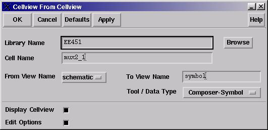
Choose Design -> Create Cellview -> From Cellview.... The Cellview From Cellview form should default to the correct values. Verify the following:
Library Name: EE451 (or EE445)
Cell Name: mux2_1
From View Name: schematic
To View Name: symbol
Tool / Data Type: Composer-Symbol
Display Cellview and Edit Options: selected

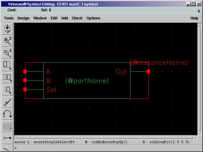
Press OK. A new schematic looking window will open up. It contains a box representing your 2:1 mux with the correct input and output ports.

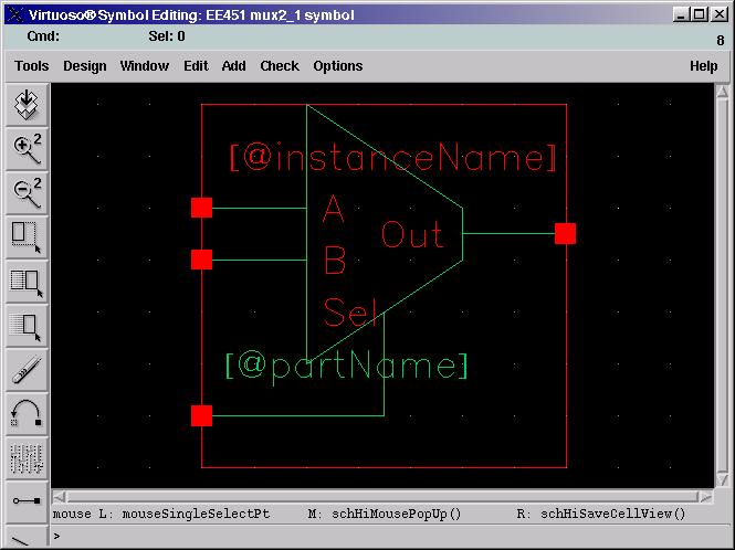
Modify the symbol to look like a normal 2:1 mux.

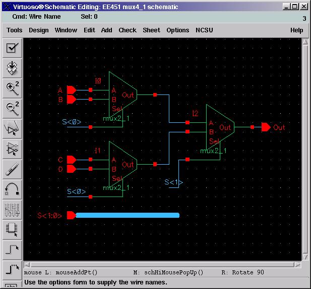
Save the symbol (f8). Close all your schematic windows until you get back to the Library Manager. Notice that you have a new view called symbol under the 2:1 mux in your Library Manager. Create a new schematic cellview in your library called mux4_1. Press i to add an instance, navigate to your library and choose mux2_1. Place three of them in your schematic. Finish the design of the 4:1 mux by making it look like the schematic below. A few things about the schematic:
- Create a bus by selecting Add -> Wire (wide) or by pressing W. Name busses using angle brackets. Your two bit selection bus is named S<1:0>.
- Wires with the same name are connected. To name a wire choose Add -> Wire Name... or press l. Add wire names the same way you add pins. The Bus Expansion option allows you to write a bus name, say S<1:0> in the names box and place each wire S<1>, S<0> individually. Play with it to see how it works.

At this point you can make a symbol of your 4:1 mux or simply simulate the current view.
Conclusion
You've successfully created a hierarchical design. Now you just need to simulate it and verify that it works like a mux. The next tutorial helps you run the simulator for your 4:1 mux.